Translate

Total Pageviews

My YouTube Channel

Wednesday, 30 April 2014

How SRM Computes Datastore Groups?

SRM determines the composition of a datastore group by the set of virtual machines that have files on the datastores in the group, and by the devices on which those datastores are stored.
When you use array-based replication, each storage array supports a set of replicated datastores. On storage area network (SAN) arrays that use connection protocols such as Fibre Channel and iSCSI, these datastores are called logical storage units (LUN) and are composed of one or more physical datastores. On network file system (NFS) arrays, the replicated datastores are typically referred to as volumes. In every pair of replicated storage devices, one datastore is the replication source and the other is the replication target. Data written to the source datastore is replicated to the target datastore on a schedule controlled by the replication software of the array. When you configure SRM to work with an SRA, the replication source is at the protected site and the replication target is at the recovery site.
A datastore provides storage for virtual machine files. By hiding the details of physical storage devices, datastores simplify the allocation of storage capacity and provide a uniform model for meeting the storage needs of virtual machines. Because any datastore can span multiple devices, SRM must ensure that all devices backing the datastore are replicated before it can protect the virtual machines that use that datastore. SRM must ensure that all datastores containing protected virtual machine files are replicated. During a recovery or test, SRM must handle all such datastores together.
To achieve this goal, SRM aggregates datastores into datastore groups to accommodate virtual machines that span multiple datastores. SRM regularly checks that datastore groups contain all necessary datastores to provide protection for the appropriate virtual machines. When necessary, SRM recalculates datastore groups. For example, this can occur when you add new devices to a virtual machine, and you store those devices on a datastore that was not previously a part of the datastore group.
A datastore group consists of the smallest set of datastores required to ensure that if any of a virtual machine's files is stored on a datastore in the group, all of the virtual machine's files are stored on datastores that are part of the same group. For example, if a virtual machine has disks on two different datastores, thenSRM combines both datastores into a datastore group. SRM also combines devices into datastore groups according to set criteria.

A virtual machine has files on two different datastores.
Two virtual machines share a raw disk mapping (RDM) device on a SAN array, as in the case of a Microsoft cluster server (MSCS) cluster.
Two datastores span extents corresponding to different partitions of the same device.
A single datastore spans two extents corresponding to partitions of two different devices. The two extents must be in a single consistency group and the SRA must report consistency group information from the array in the device discovery stage. Otherwise, the creation of protection groups based on this datastore is not possible even though the SRA reports that the extents that make up this datastore are replicated.
Multiple datastores belong to a consistency group. A consistency group is a collection of replicated datastores where every state of the target set of datastores existed at a specific time as the state of the source set of datastores. Informally, the datastores are replicated together such that when recovery happens using those datastores, software accessing the targets does not see the data in a state that the software is not prepared to deal with.

Not all SRAs report consistency group information from the storage array, because not all storage arrays support consistency groups. If an SRA reports consistency group information from the array following a datastore discovery command, the LUNs that constitute a multi-extent VMFS datastore must be in the same storage array consistency group. If the array does not support consistency groups and the SRA does not report any consistency group information, SRMcannot protect virtual machines located on on the multi-extent datastore.
Info taken from VMware documentation

Tuesday, 29 April 2014

How Does vSphere Replication Work?

With SRM 5 we introduced a new alternative for replication of virtual machines called "vSphere Replication" or "VR" for short.  There has been some excellent conversation about VR generated by presentations at VMworld and the release of SRM on the 15th of September.
We've also received a lot of questions about the details of VR, and thought this would be an excellent venue and opportunity to give you some more detail on how it actually works behind the scenes to protect your VMs.

What is vSphere Replication?

It is an engine that provides replication of virtual machine disk files that tracks changes to VMs and ensures that blocks that differ within a specified recovery point objective are replicated to a remote site.

How does VR work?

Fundamentally, VR is designed to continually track I/O destined for a VMDK file and keep track of what blocks are being changed.  There is a user-configured Recovery Point Objective for every VMDK, and the job of VR is to ensure that the blocks that change are copied across the network to the remote site at a rate sufficient to keep the replica in synch with the primary in accordance with the configured RPO.
If VR is successful in doing so, the replica at the remote site will be able to be recovered as part of a recovery plan within SRM.

How do you configure VR?

This is not very difficult at all!  There are a few places you can configure VR for a VM or set of VMs, either from within SRM or even by directly editing the properties of the VM from within the vSphere Client.
For example, you can right-click on a VM and select "vSphere Replication" as one of the popup menu items:
VR-for-VM
Once you select VR properties you can choose an RPO, a source VMDK, target folder, or even a pre seeded copy of the VM at the remote site to act as the replica!
Rep-Settings
 

How VR determines what is different and what needs to be replicated

There are two forms of synchronization that VR will use to keep systems synchronized.  When VR is first configured for a virtual machine you can choose a primary disk file or set of disk files and a remote target location to hold the replica.  This can be an empty folder, or it can be a copy of the VMDK that has the same UUID as the primary protected system.
The first thing VR will do when synchronizing is read the entire disk of both the protected and recovery site and generate a checksum for each block.  It then compares the checksum mapping between the two disk files and thereby creates an initial block bundle that needs to be replicated on the first pass to bring the block checksums into alignment.  This happens on port 31031.
This is called a "full synch" and only happens very rarely: Usually just on the first pass when the VM is configured for VR, but can also happen occasionally during other situations such as when recovering from a crash.
The ongoing replication is by use of an agent and vSCSI filter that reside within the kernel of an ESXi 5.0 host that tracks the I/O and keeps a bitmap in memory of changed blocks and backs this with a "persistent state file" (.psf) in the home directory of the VM.  The psf file contains only pointers to the changed blocks.  When it is time to replicate the changes to the remote site, as dictated by the RPO set for the vmdk, a bundle is created with the blocks that are changed and this is sent to the remote site for committing to disk.  This replication happens on port 44046.

How is the schedule for replication determined?  Can I create my own schedules?

You can not create your own schedules for replication, because there is a lot of intelligence built into the algorithm used by VR to ship blocks.  
Based on the RPO that acts as the outside window for replication, VR will attempt to send blocks using some dynamic computation to figure out how aggressively it needs to send data.
If, for example, the RPO is set for 1 hour and there is a very small historical change rate to blocks, VR does not need to act aggressively.  We take into account the last 15 transfers to the remote site to calculate on average how much data is likely to be shipped in the current bundle.  If the data took on average for example 10 minutes to ship and commit we estimate that we will not need more than 10 minutes for the next set of data and can schedule a start time to initiate the next transfer some time below 49 minutes to stay within the 1 hour RPO. 
If, however, the RPO is set to 1 hour and we historically are taking 35 minutes to ship and commit, then we know that eventually we will exceed our RPO as that extra 5 minutes beyond the half-way point will eventually catch up to our RPO even if we start shipping blocks immediately on completion of the previous bundle!
So the point is that VR takes all of these factors into account and will set its own schedule to ship changed block bundles, depending on a number of factors such as how large the transfer size is, how much change is taking place, how long it has taken in the past to ship, and so forth, and will adjust or set alerts accordingly.

How data gets transferred and how it gets written

Because the VR agent works with a passive filter that tracks changes, all we worry about is changed blocks, not the format of the disk or file system or anything.  
At the recovery site you will need to deploy a virtual appliance called the "vSphere Replication Server" (VRS) that acts as the target for the VR agent.  The VRS receives the blocks from the agents at the protected site and waits until the bundle is completely received and consistent, then passes it off to the ESXi's network file copy (NFC) service to write the blocks to its target storage that we specified when we configured VR for the protected VM.  The result is that the entire process is abstracted from the storage until the blocks are given to the NFC and that means we can mix and match storage: We can have thick or thin provisioned VMDKs on either site, and use any type of storage we choose at either site.  The NFC of the host the VRS interacts with just writes to a VMDK.  In essence, the VRS receives the block transfer, the NFC writes it out.  It's important to note that the traffic from the VR agent is sent across the vmkernel management NICs of your ESXi hosts, so be aware you will see a lot more traffic on those switches.
Hopefully this gives you a little more insight into how vSphere Replication works.  If you've got questions or want more detail, please leave a note in the comments!  If you think vSphere Replication is great or 'not' please let me know that as well, and let's talk about why you think what you do.
We've got high hopes that VR will give our smaller customers a new capability to approach DR, and our larger customers the ability to tier out their replication offerings.
Info taken from blogs.vmware.com
Thanks to

Sunday, 27 April 2014

vVOL

Disclaimer : This a Technology Preview. This functionality is not available at the moment. It is simply demonstrating the exciting prospects that the future holds for storage related operations within the virtual world.
Following on from some of the major storage announcements made at VMworld 2012 this year, I wanted to give you an overview of thevirtual volumes feature in this post. Virtual Volumes is all about making the storage VM-centric – in other words making the VMDK a first class citizen in the storage world. Right now, everything is pretty much LUN-centric or volume-centric, especially when it comes to snapshots, clones and replication. We want to change the focus to the VMDK, allowing you to snapshot, clone or replicate on a per VM basis from the storage array. Historically, storage admins and vSphere admins would need to discuss up front the underlying storage requirements of an application running in a VM. The storage admin would create a storage pool on the array, set features like RAID level, snapshot capable, replication capable, etc. The storage pool would then be carved up into either LUNs or shares, which would then be presented to the ESXi hosts. Once visible on the host, this storage could then be consumed by the VM and application.
What if the vSphere admin could decide up front what the storage requirements of an application are, and then tell the array to create an appropriate VMDK based on these requirements? Welcome to VVOLs.
My colleague Duncan did a super write up on the whole VVOL strategy in his post here. In this post he also directs you to the VMworld sessions (both 2011 & 2012) which discuss the topic in greater detail. What I wished to show you in this post are the major objects and their respective roles in VVOLs. There are 3 objects in particular; the storage provider, the protocol endpoint and the storage container. Let’s look at each of these in turn.
Storage Provider: We mentioned the fact that a vSphere admin create a set of storage requirements for an application/VM. How does an admin know what an array is capable of offering in terms of performance, availablity, features, etc? This is where the Storage Provider comes in. Out of band communication between vCenter and the storage array is achieved via the Storage Provider. Those of you familiar with VASA will be familiar with this concept. It allows capabilities from the underlying storage to be surfaced up into vCenter. VVOLs uses this so that storage container capabilities can be surfaced up. But there is a significant difference in VVOLs – we can now use the storage provider/VASA to push information down to the array also. This means that we can create requirements for our VMs (availability, performance, etc) and push this profile down to the storage layer, and ask it to build out the VMDK (or virtual volume) based on the requirements in the profile. The Storage Provider is created by the storage array vendor, using an API defined by VMware.
Protocol Endpoint:Since the ESXi will not have direct visibility of the VVOLs which back the VMDKs, there needs to be an I/O demultiplexor device which can communicate to the VVOLs (VMDKs) on its behalf. This is the purpose of the protocol endpoint devices, which in the case of block storage is a LUN, and in the case of NAS storage is a share or mountpoint. When a VM does I/O, the I/O is directed to the appropriate virtual volume by the protocol endpoint. This now allows us to scale to very, very many virtual volumes, and the multipathing characteristics of the protocol endpoint device are implicitly inherited by the VVOLs.
Storage Container: This is your storage pool on the array. Currently, one creates a pool of physical spindles on an array, perhaps building a raid across them and then carves this up into LUNs or shares to be presented to the ESXi hosts. In VVOLs, only the container/pool needs to be created. Once we have the storage provider and protocol endpoints in place, the storage container becomes visible to the ESXi hosts. From then on, as many VVOLs can be created in the container as there is available space, so long as the characteristics defined in the storage profiles matches the storage container.


Now, this is a project that can only be successful if our storage partners engage with us to make it a success. I’m pleased to say that many of our storage partners are already working with us on the first phase of this project, with many more on-boarding as we speak. And admittedly the video above is more about the architecture of VVOLs and doesn’t really show off the coolness of the feature. So I’d urge you to look at the following posts from some of our partners. EMC’s Chad Sakac has a post here around how they are integrating with virtual volumes, and HP’s Calvin Zito shows how their 3PAR array is integrated with this post. Interestingly, the title in both posts is around the future of storage. I think VVOLs is definitely going to change the storage landspace.

Information taken from blogs.vmware.com

Saturday, 26 April 2014

Two Available VCAP5-DCA Exams


On April 7, we released a new exam to qualify candidates for the VMware Certified Advanced Professional 5 - Data Center Administration (VCAP5-DCA) Certification.
This new exam (exam code VDCA550) is based on vSphere v5.5, where the existing exam (exam code VDCA510) is based on vSphere v5.0.
Passing either of these exams will earn VCAP5-DCA certification if you meet the other pre-requisites.


vSphere 5.5 Based Exam – Exam Code VDCA550

vSphere 5.0 Based Exam – Exam Code VDCA510


Recommended Courses

The following VMware courses can help you prepare for the VCAP5-DCA exam but are not required:

Friday, 25 April 2014

Does cores per socket Affect Performance?

This is one of the very good post available on the blogs.vmware.com. I hope this will be helpful for all of us to understand the Performance Impact of Cores per Socket.

There is a lot of outdated information regarding the use of a vSphere feature that changes the presentation of logical processors for a virtual machine, into a specific socket and core configuration. This advanced setting is commonly known as corespersocket.


It was originally intended to address licensing issues where some operating systems had limitations on the number of sockets that could be used, but did not limit core count.
It’s often been said that this change of processor presentation does not affect performance, but it may impact performance by influencing the sizing and presentation of virtual NUMA to the guest operating system.
Reference Performance Best Practices for VMware vSphere 5.5 (page 44):http://www.vmware.com/pdf/Perf_Best_Practices_vSphere5.5.pdf

Recommended Practices

#1 When creating a virtual machine, by default, vSphere will create as many virtual sockets as you’ve requested vCPUs and the cores per socket is equal to one. I think of this configuration as “wide” and “flat.” This will enable vNUMA to select and present the best virtual NUMA topology to the guest operating system, which will be optimal on the underlying physical topology.
#2 When you must change the cores per socket though, commonly due to licensing constraints, ensure you mirror physical server’s NUMA topology. This is because when a virtual machine is no longer configured by default as “wide” and “flat,” vNUMA will not automatically pick the best NUMA configuration based on the physical server, but will instead honor your configuration – right or wrong – potentially leading to a topology mismatch that does affect performance.
To demonstrate this, the following experiment was performed. Special thanks to Seongbeom for this test and the results.

Test Bed

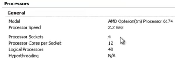
Dell R815 AMD Opteron 6174 based server with 4x physical sockets by 12x cores per processor = 48x logical processors.
TestBed
The AMD Opteron 6174 (aka Magny-Cours) processor is essentially two 6 core Istanbul processors assembled into a single socket. This architecture means that each physical socket is actually two NUMA nodes. So this server actually has 8x NUMA nodes and not four, as some may incorrectly assume.
Within esxtop, we can validate the total number of physical NUMA nodes that vSphere detects.
8NUMANodes
Test VM Configuration #1 – 24 sockets by 1 core per socket (“Wide” and “Flat”)
VMTest1
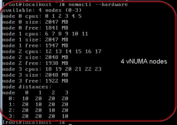
Since this virtual machine requires 24 logical processors, vNUMA automatically creates the smallest topology to support this requirement being 24 cores, which means 2 physical sockets, and therefore a total of 4 physical NUMA nodes.
Within the Linux based virtual machine used for our testing, we can validate what vNUMA presented to the guest operating system by using: numactl –hardware
VMTest1NUMA
Next, we ran an in-house micro-benchmark, which exercises processors and memory. For this configuration we see a total execution time of 45 seconds.
VMTest1Result
Next let’s alter the virtual sockets and cores per socket of this virtual machine to generate another result for comparison.
Test VM Configuration #2 – 2 sockets by 12 cores per socket
VMTest2
In this configuration, while the virtual machine is still configured have a total of 24 logical processors, we manually intervened and configured 2 virtual sockets by 12 cores per socket. vNUMA will no longer automatically create the topology it thinks is best, but instead will respect this specific configuration and present only two virtual NUMA nodes as defined by our virtual socket count.
Within the Linux based virtual machine, we can validate what vNUMA presented to the guest operating system by using: numactl –hardware
TestVM2NUMA
Re-running the exact same micro-benchmark we get an execution time of 54 seconds.
TestVM2Result
This configuration, which resulted in a non-optimal virtual NUMA topology, incurred a 17% increase in execution time.
Test VM Configuration #3 – 1 socket by 24 cores per socket
TestVM3
In this configuration, while the virtual machine is again still configured have a total of 24 logical processors, we manually intervene and configured 1 virtual socket by 24 cores per socket. Again, vNUMA will no longer automatically create the topology it thinks is best, but instead will respect this specific configuration and present only one NUMA node as defined by our virtual socket count.
Within the Linux based virtual machine, we can validate what vNUMA presented to the guest operating system by using: numactl –hardware
TestVM3NUMA
Re-running the micro-benchmark one more time we get an execution time of 65 seconds.
TestVM3Result
This configuration, with yet a different non-optimal virtual NUMA topology, incurred a 31% increase in execution time.
To summarize, this test demonstrates that changing the corespersocket configuration of a virtual machine does indeed have an impact on performance in the case when the manually configured virtual NUMA topology does not optimally match the physical NUMA topology.

The Takeaway

Always spend a few minutes to understand your physical servers NUMA topology and leverage that when rightsizing your virtual machines.
Other Great References:
Source:-
Thanks to

Wednesday, 23 April 2014

How to Force a VM to ask for the answers for AnswerVM API Demonstration?

1. Connect with that esxi host shell where the vm is created through Putty (SSH Client) and then edit the .vmx file of that vm where you want input should be asked:-
 

2. Locate this attribute and change this UUID to any other value like in this demo I changed it from 59 to 54. You can use any value here. Once changed save the file and exit from here:-

 
3. Finally power on the VM either from GUI or CLI. In this demo I used CLI from vMA I tried to poweron the vm and then it got stuck there and then I used the another command to give the answer. All the commands are given here in this screenshot:-
 
 
That's done. That's how you can force the VM to ask for the answers.